Of course, as promised this topic is retaken, now we will get into more details, particularly about State Diagrams, Package Diagrams and Component Diagrams.
As previously seen, these diagrams work as a way of representing the different parts of a project and its relationships, let’s start talking about the first one, State Diagram.
According with GeeksforGeeks «a state diagram is used to represent the condition of the system or part of the system at finite instances of time.

It’s a behavioral diagram and it represents the behavior using finite state transitions.
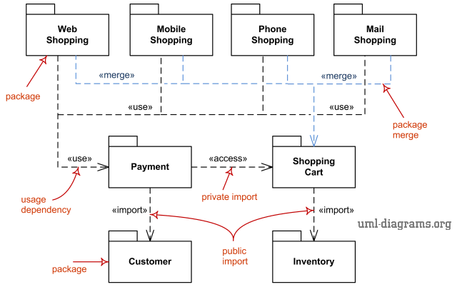
Now let us talk about Package Diagrams, here’s a page with more information about it, a little summary follows:
Package diagram is a UML structure diagram which shows structure of the designed system at the level of packages, it shows the arrangement and organization of model elements in middle to large scale project. The following elements are typically drawn in a package diagram: package, packageable element, dependency, element import, package import, package merge.
Now, let’s look at the last one: «UML Component diagrams are used in modeling the physical aspects of object-oriented systems that are used for visualizing, specifying, and documenting component-based systems and also for constructing executable systems through forward and reverse engineering. Component diagrams are essentially class diagrams that focus on a system’s components that often used to model the static implementation view of a system». Visual Paradigm tells everything about this last kind of diagrams.
This concludes our entries about UML, we will keep creating content for your knowledge to keep growing. Thanks for following us until here.
-RC
